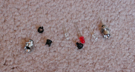
| These are some of the parts I had to
pick from to use for the hard drive and power-on LED's. I thought the
chrome would look nice with the clear case so that's what I used. The
little black round things are to be used in sheet metal and were not
quite thick enough for the 3/16" Plexiglas.
|
|
|
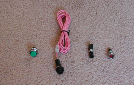
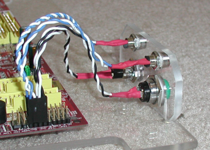
And these are some of the buttons I
picked up and again I went with the chrome ones. The reset button
is recessed (far right) so that would work great and the green one will be used for the
power on button.
|
|
|
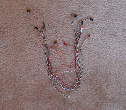
Here is a bunch of wire I used for this part of the project.
I bought these at the computer show at the
time I was getting some other stuff for this system. I wanted these
because they already had connectors on them which will attach to the
motherboard. After measuring the length I
needed, out comes the cutters. Now it's time to get to the soldering
iron and and get to work.
|
|
|
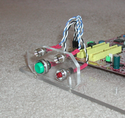
The front panel is made out of
3/16" Plexiglas which is screwed to the motherboard shelf. I also added some
red heat shrink tubing to cover
the solder joints. It's nice to be able to make these just the right
length which makes for a clean look.
The buttons and LED's will go through the front of the case.
|
|
|
|
Now it's time to work on the power supply....oh yeah....I
messed that as well. |
|
1
2
3
4
5
6
7
8
9
10
11
12 |