|
Working With Metal Continued
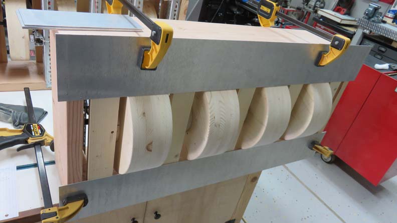
I cut the top and bottom pieces first and clamped them in place for
test fitting. I left them long by about one inch per side.
|
|
 |
|
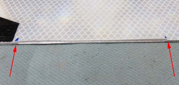
This is the back of the top piece. What you see here
(between the arrows) is
a chamfer that I put on to just clear the wheels. The reason for this is
so I can get this trim piece as close as possible to the wheel so people
can't see inside of it. This helped quite a bit and I did it for each
wheel position.
|
|
 |
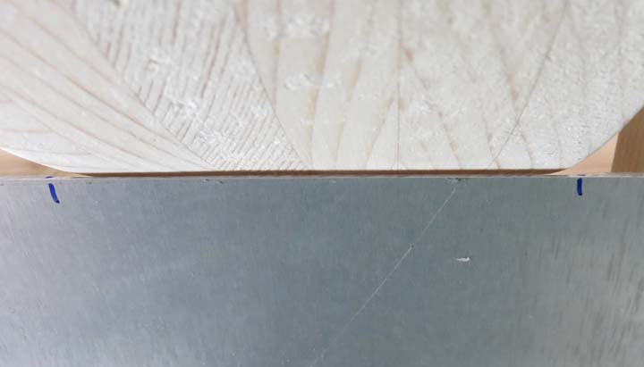
That gap between the wheel and trim piece is less than 1/16" and is working out very nicely.
|
|
 |
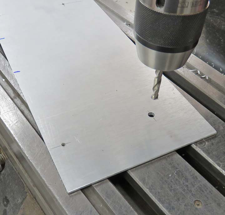
Now it's time to fasten the trim plates to the frame. I laid out some
hole locations and drilled pilot holes for the screws first.
|
|
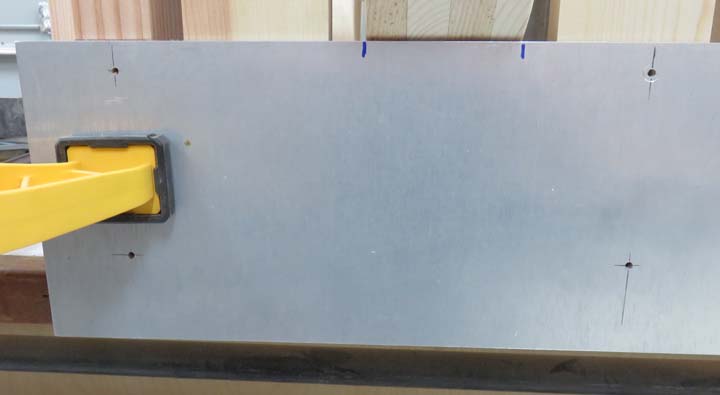 |
Then I opened up all the holes to 1/4" for some #10 screws. Again, this
is oversize but it's for adjustment.
|
|
 |
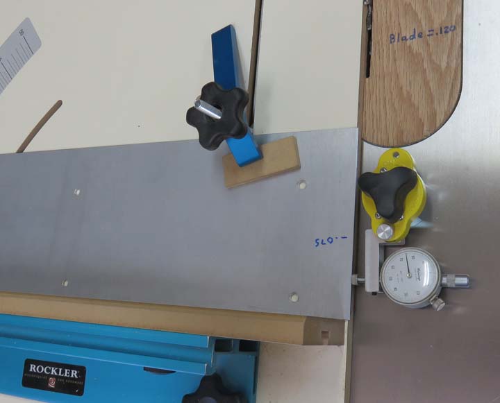
I'm trimming off a small amount so both sides overhang the same amount
on the top and bottom.
|
|
 |
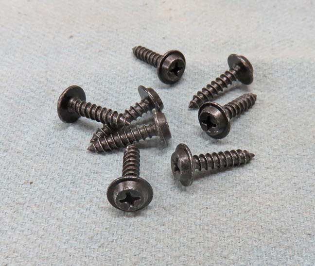
Here are the screws that I'll be using. They are #10 X 3/4" long, have
an oversize head and are black oxide plated.
|
|
 |
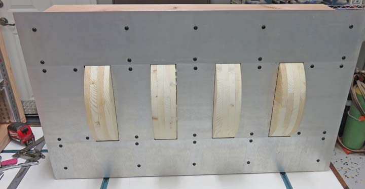
Here is what it looks like with all the trim pieces installed. The gaps
are very small all over, and should look good once it's all painted. Now
it's time to install some magnets.
|
|
 |
|
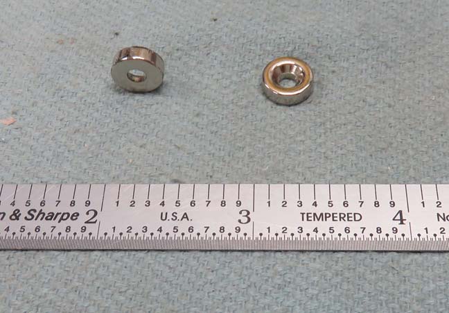
Reed Switches
As I've said earlier, the Reed switches work with
magnets, but I didn't want to use the ones that came with mine. I bought
some 1/2" diameter X 1/8" thick neodymium magnets. Plus these have a
chamfer for a #4 screw which should work perfect for my application.
|
|
 |
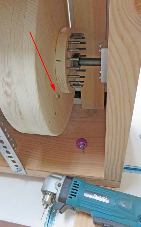
I used my right-angle drill for the pilot hole and then fastened the
magnet to the wheel.
|
|
 |
|
1
2
3
4
5
6
7
8
9
10
11
12
13 |