|
Working With Metal Continued
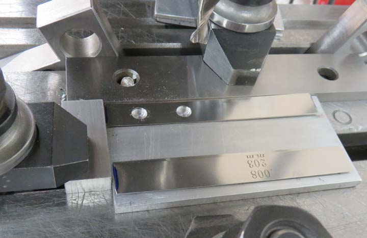
I machined two pieces at a time and used two more pieces next to them
to make sure my clamp plate stayed flat. The holes are 3/4" apart which
was needed to work with the material below.
|
|
 |
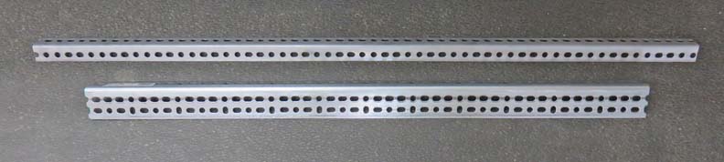
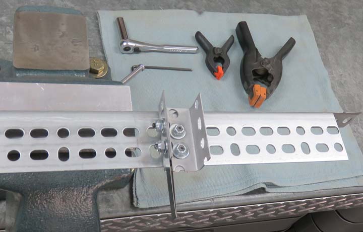
This material is called "Slotted Angle" and I'm
using two different sizes. The top one is 1" square, and the bottom one
is 1 1/4" X 2 1/4" with both having the slots 3/4" apart.
|
|
 |
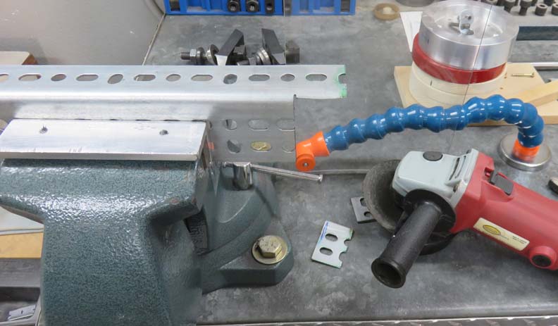
I'm trimming the ends of the larger angle so it will fit inside the
frame. This will make for a better fit.
|
|
 |
|
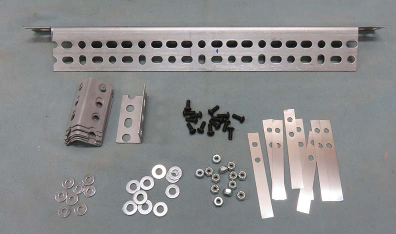
With the ends of the larger angle trimmed, I'm ready to
start assembly. Below the larger piece at the top, I cut the 1" square
angle into 3" lengths. Next to that are some 10-32 button head cap
screws along with some locking nuts.
I'm using two different sizes of flat washers, #10's and
1/4". The reason for that is because the slots in the angle are just
larger than my #10 washers so I'll be using them stacked upon another.
Last but not least, is the .008" shims that will be
used, two per wheel.
|
|
 |
|
I did my assembly using my bench vise as it acted like a
third hand. You can also see how I'm using two pieces of the smaller
angle, creating a U shape. One angle is for the .008" shims, and the other
will be used to hold a Reed Switch. If you look close you can see two shims
are being used, one on each side of the angle.
|
|
 |
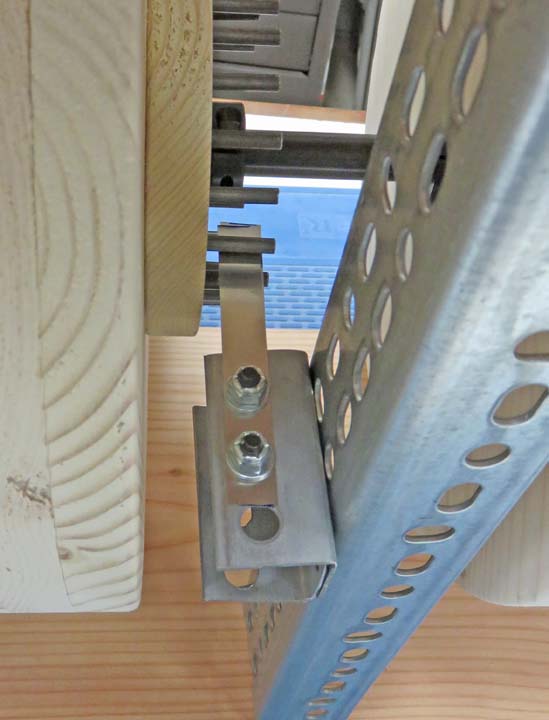
Here is what it looks like mounted. Now you might ask, "why did I use
such small screws if you have larger slots"? This is to aid in moving
things around as needed. In other words, adjustability.
|
|
 |
|
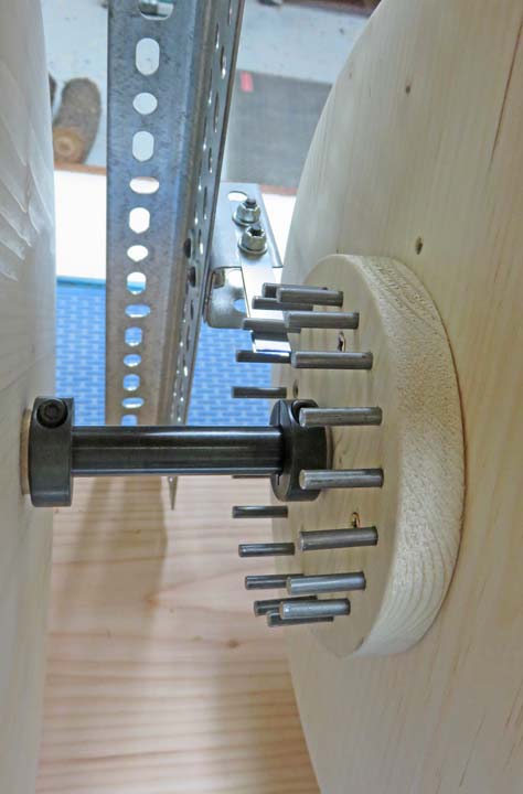
A view from the other side. The shims click when the wheel turns every 1
1/2" which should work out nicely. If you're old enough to
remember, think playing cards in your bicycle spokes and you'll get the
idea here.
|
|
 |
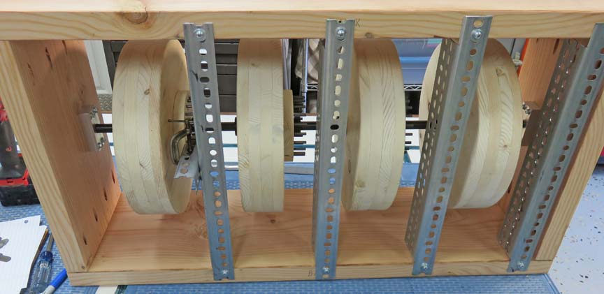
Now you can see how the slotted angle fits with the long side resting on
the inside of the frame.
|
|
 |
|
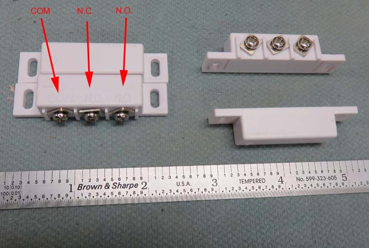
The next item to attach to the slotted angle will be a
Reed Switch. I'm sure most of you have seen this type of switch before
because they are used in burglar alarms. Inside the piece with the three
screws is the switch. The piece without screws is the magnet. When the
switch is next to the magnet, it moves the contact inside and either
'opens' or 'closes' the circuit. One wire goes to the COM or common terminal and the
other wire goes to the N.C. (normally closed) or the N.O. (normally
open) terminal, depending on your needs. However, I won't be using the
magnets that came with these switches, I have something else in mind.
|
|
 |
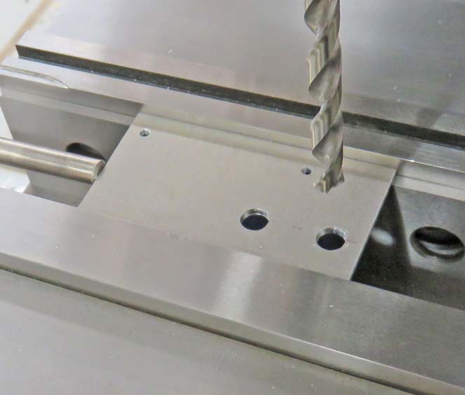
To hold the Reed Switches, I had to make some brackets. The two smaller
holes are for the switch and the two larger holes (1/4") are to mount
the bracket to the slotted angle.
|
|
 |
|
1
2
3
4
5
6
7
8
9
10
11
12
13 |